Last updated on January 31st, 2023 at 10:37 am
Ignition switch wiring color code: Interestingly, a vehicle’s ignition switch is responsible for powering up or turning off the electrical circuits through the key operation switch known as the starter switch.
The ignition switch controls the functioning of other related components, such as; starters, ignition coils, and other accessories.
Being a controller of your vehicle’s electrical system, the ignition switch’s wiring, terminals, and the connection is essential knowledge that would necessitate a successful installation, wiring, and rewiring of the ignition switch.
Notwithstanding, familiarity with the ignition switch color codes is paramount before you begin any installation and wiring of any electrical components, even the ignition switch itself.
Remember that the wiring code of some vehicles may differ in terms of model or country, so what could your ignition wiring color code be?
Be patient; this article will also proffer answers to these specific queries ranging from; what color are the ignition switch wires, what is R1 and R2 on the ignition switch, which wire should an ignition acc connect to, what does the ignition switch connect to, which color wires go together, what wire goes from ignition to starter, and finally the list of ignition switch wiring color code,. Read this also: What Wires Go To Ignition Switch?
Let’s get started!
What Color Are The Ignition Switch Wires?
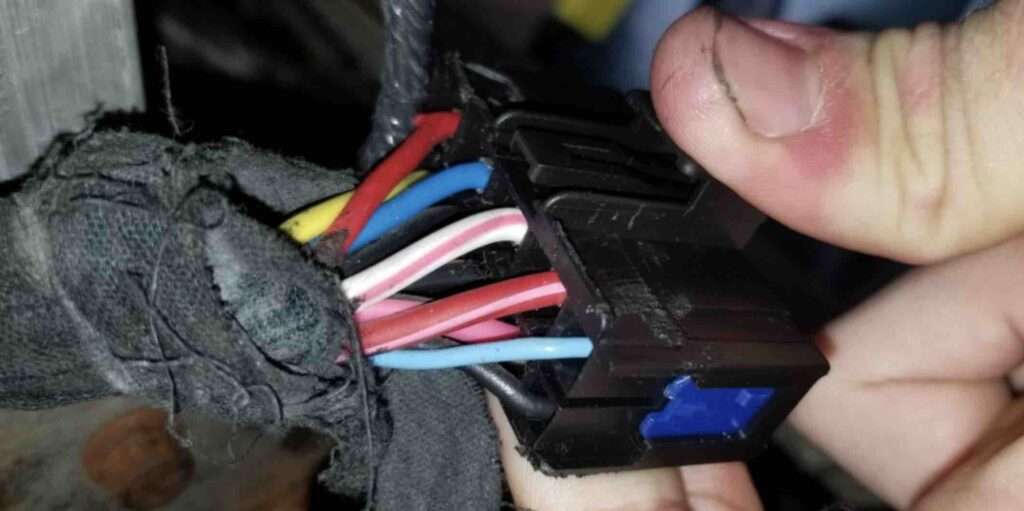
The color of the ignition switch wires might slightly differ due to vehicle models or countries, but from a general perspective, they are;
- Yellow color – for the battery connections.
- The blue color – is for the ignition system.
- The green color is for the starter connections.
- Red color for accessories connections.
Essentially, each of the above color wires serves a specific purpose in the ignition switch as regards the pole terminals; BATT for the battery wire, ST for the starter wire, IGN for the ignition wire, and ACC for accessories, all at the back of the ignition switch.
What Is R1 And R2 On Ignition Switch?
The R1 and R2 terminals on the ignition switch represent the glow plug in the accessory of a tractor, Nissan, and Datson ignition switches. In a Nissan or Datson ignition switch, R1 and R2 might come on together, or if one came on when the RUN position is selected, the other would come on in the START position.
Which Wire Should An Ignition ACC Connect To?
The wire which should connect to the ACC is the accessory wire (red). The ACC terminal is functional with the accessories at the ignition switch’s upper side, which help power the fans, lights, radio, and power windows, to mention a few.
What Does The Ignition Switch Connect To?
The ignition switch is connected to the starter to activate it. Hence, a starter is an electric motor that enhances the cranks in the engine; Also, it improves the proper starting of the vehicle when activated by the ignition switch and is in the steering column of a car.
Which Color Wires Go Together?
The color wires that go together are: white & red goes together while white & black go together in the ignition switch.
What Wire Goes From Ignition To Starter?
The wire that goes from the ignition to the engine starter is the ST terminal, which should be green in color. However, the function of this wire is to help the solenoid start the engine of the vehicle.
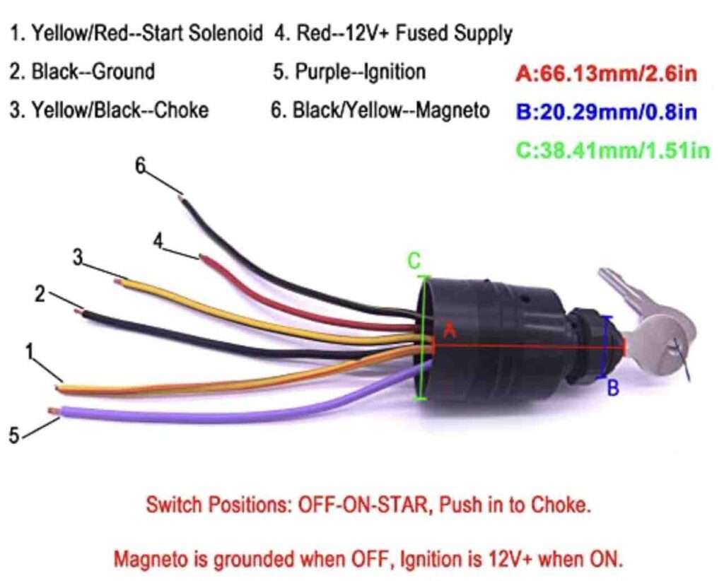
List Of Ignition Switch Wiring Color Code, Colors
Check out the list of switch wiring color codes below;
- The blue wire is for the ignition system, like the coil connected to the IGN terminal.
- The yellow wire is the battery connection attached to the BATT terminal.
- The red wire is for the accessory connection attached to the ACC terminal.
- The green wire is for the starter connection connected to the ST terminal.
OTHER GENERAL WIRING COLOR CODE
| Color | Use |
| Green or green w/yellow stripe(s) | DC Grounding Conductors |
| Black or Yellow | DC Negative Conductors |
| Red | DC Positive Conductors |
Engine and Accessory Wiring Color Code
| Colour | Item Use | |
| Yellow w/red strip (YR) | Starting circuit | Start switch of solenoid |
| Brown/yellow stripe (BY) or Yellow(Y) – see note | Bilge blowers | Fuse or blowers switch |
| Dark Gray (Gy) | Navigation lights | Fuse or switch to lights |
| Tachometer | Gauge Tachometer sender | |
| Brown (Br) | Generator armature | Generator armature to regulator |
| Alternator charge light | Generator | |
| Terminal/alternator | ||
| Auxiliary terminal to light toregulator | ||
| Pumps | Fuse or switch to pumps | |
| Orange (O) | Accessory feed | Ammeter to alternator or generatoroutput and accessory fuses or switches |
| Distribution panel to accessoryswitch | ||
| Purple (Pu) | Ignition | electrical instruments and Ignition switch to coil. |
| Instrument feed | Distribution panel with electricinstruments | |
| Dark blue | Cabin and instrument lights | A switch to lights or fuse |
| Light blue (Lt Bl) | Oil pressure | Oil pressure sender to gauge |
| Tan | Water temperature | Water temperature sender to gauge |
| Pink (Pk) | Fuel gauge | Fuel gauge sender to gauge |
| Green/stripe (G/x) | Tilt down and/or trim in | Tilt and/or trim circuits |
| Except G/Y | ||
| Blue/stripe (Bl/x) | Tilt up and/or trim out | Tilt and/or trim circuits |
Conclusion
To summarize this write-up, the ignition switch wires are vital to differentiate color and function, enabling you to rewire your ignition switch successfully when needed.
So far, you have understood that the ignition switch has four basic wiring systems; perchance, this wiring and color might vary due to the country. These four primary wires are attached to the poles/terminals like; the ignition IGN, battery BATT, accessory ACC, and the starter ST of the switch.
Essentially, ignition switch wiring is simple and requires you to match the wire’s color to the correct ignition switch terminals. Always ensure you have a manufacturer’s guide for valid wire color codes, or you could contact a technician to help you out in any case. Do well to share this guide with others!
Related: How To Do 4 Pin & 7 Way Trailer Plug Wiring Diagram with Brakes

Hi dear, I am Dennis Gift, an autobody repair technician with over 4 years of experience; and I love everything about fitness and cars and researching and sharing my experience. And this is where I get to do that freely without reservations. So come along with me.

